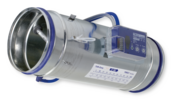
VAV terminal unit Type TVR/160/Easy

Circular VAV terminal units for standard applications regarding the supply air or extract air control in variable air volume systems
Optional equipment and accessories
Application
Special characteristics
Nominal sizes
Variants
Construction
Parts and characteristics
Attachments
Accessories
Useful additions
Construction features
Materials and surfaces
Galvanised sheet steel construction
Powder-coated construction (P1)
Stainless steel construction (A2)
Variant with acoustic cladding (-D)
Mineral wool
Standards and guidelines
Maintenance
Functional description
The VAV terminal unit is fitted with a differential pressure sensor for measuring the volume flow rate.
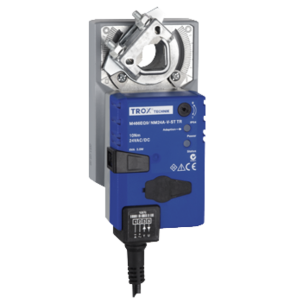
The control components (attachments) include a differential pressure transducer that transforms the differential pressure (effective pressure) into an electric signal, a controller, and an actuator; the control functions can be achieved with an Easy controller, with a Compact controller, or with individual components (Universal or LABCONTROL).
For most applications, the setpoint value comes from a room temperature controller.
The controller compares the actual value with the setpoint value and alters the control signal of the actuator if there is a difference between the two values.
Volume flow rate ranges
The minimum differential pressure of VAV terminal units is an important factor in designing the ductwork and in rating the fan including speed control.
Sufficient duct pressure must be ensured for all operating conditions and for all control units. The measurement points for fan speed control must be selected accordingly.
The volume flow rates given for VAV terminal units depend on the nominal size and on the control component (attachment) that is installed. The table gives the minimum and maximum values for a VAV terminal unit. Some control components may only have a limited volume flow rate range. This applies in particular to control components with a static differential pressure transducer. For volume flow rate ranges for all control components refer to our Easy Product Finder design programme.
l/s | m³/h | ① Pa | ② Pa | ③ Pa | ④ Pa | ± % | |
Nominal sizes | 100 – 400 mm |
Volume flow rate range | 10 – 1680 l/s or 36 – 6048 m³/h |
Volume flow rate control range (unit with dynamic differential pressure measurement) | Approx. 10 to 100% of the nominal volume flow rate |
Minimum differential pressure | 5 – 90 Pa |
Maximum differential pressure | 1000 Pa |
Operating temperature | 10 – 50 °C |
Quick sizing tables provide a good overview of the room sound pressure levels that can be expected. Approximate intermediate values can be interpolated. Precise intermediate values and spectral data can be calculated with our Easy Product Finder design programme.
The first selection criteria for the nominal size are the actual volume flow rates Vmin and Vmax. The quick sizing tables are based on generally accepted attenuation levels. If the sound pressure level exceeds the required level, a larger air terminal unit and/or a silencer is required.
TVR, Sound pressure level at differential pressure 150 Pa
100 | 10 | 36 | 32 | 20 | <15 | <15 | <15 | <15 |
100 | 40 | 144 | 45 | 36 | 28 | 26 | 25 | 18 |
100 | 65 | 234 | 51 | 41 | 33 | 31 | 31 | 24 |
100 | 95 | 342 | 54 | 42 | 33 | 31 | 36 | 27 |
125 | 15 | 54 | 33 | 22 | <15 | <15 | <15 | <15 |
125 | 60 | 216 | 45 | 36 | 30 | 28 | 25 | 17 |
125 | 105 | 378 | 49 | 40 | 34 | 32 | 31 | 21 |
125 | 150 | 540 | 52 | 41 | 34 | 32 | 35 | 24 |
160 | 25 | 90 | 40 | 28 | 20 | 16 | 20 | <15 |
160 | 100 | 360 | 47 | 39 | 34 | 31 | 28 | 19 |
160 | 175 | 630 | 50 | 42 | 37 | 34 | 32 | 23 |
160 | 250 | 900 | 53 | 44 | 39 | 36 | 37 | 28 |
200 | 40 | 144 | 40 | 31 | 23 | 20 | 20 | <15 |
200 | 160 | 576 | 47 | 40 | 34 | 33 | 29 | 15 |
200 | 280 | 1008 | 50 | 44 | 40 | 38 | 32 | 21 |
200 | 405 | 1458 | 54 | 45 | 39 | 38 | 38 | 25 |
250 | 60 | 216 | 37 | 28 | 22 | 20 | 20 | <15 |
250 | 250 | 900 | 47 | 40 | 34 | 33 | 35 | 18 |
250 | 430 | 1548 | 48 | 42 | 38 | 37 | 37 | 25 |
250 | 615 | 2214 | 52 | 44 | 38 | 37 | 42 | 29 |
315 | 105 | 378 | 42 | 35 | 28 | 25 | 28 | <15 |
315 | 410 | 1476 | 47 | 42 | 35 | 34 | 39 | 21 |
315 | 720 | 2592 | 49 | 44 | 39 | 38 | 42 | 28 |
315 | 1030 | 3708 | 53 | 48 | 42 | 41 | 46 | 35 |
400 | 170 | 612 | 43 | 36 | 30 | 26 | 30 | <15 |
400 | 670 | 2412 | 44 | 38 | 32 | 30 | 37 | 21 |
400 | 1175 | 4230 | 47 | 42 | 36 | 35 | 41 | 29 |
400 | 1680 | 6048 | 50 | 44 | 38 | 37 | 46 | 33 |
① TVR
② TVR with secondary silencer CS/CF, insulation thickness 50 mm, length 500 mm
③ TVR with secondary silencer CS/CF, insulation thickness 50 mm, length 1000 mm
④ TVR with secondary silencer CS/CF, insulation thickness 50 mm, length 1500 mm
⑤ TVR-D
Circular VAV terminal units for variable and constant air volume systems, suitable for supply or extract air, available in seven nominal sizes.
High control accuracy (even with upstream bend R = 1D).
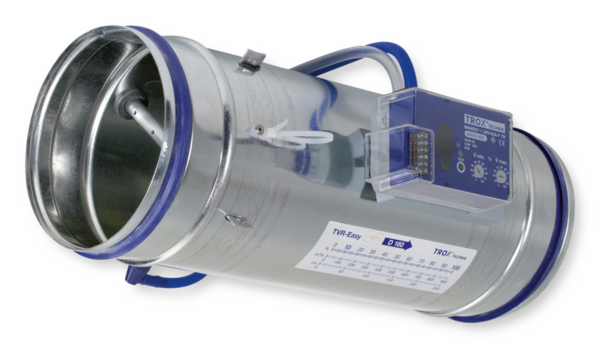
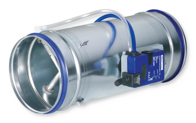
Ready-to-commission unit which consists of the mechanical parts and the electronic control components. Each unit contains an averaging differential pressure sensor for volume flow rate measurement and a damper blade. Factory assembled control components complete with wiring and tubing.
Differential pressure sensor with 3 mm measuring holes (resistant to dust and pollution)
Spigot with groove for lip seal, suitable for connecting ducts according to EN 1506 or EN 13180.
Position of the damper blade indicated externally at shaft extension.
Closed blade air leakage to EN 1751, class 4 (nominal size 100, class 2; nominal sizes 125 and 160, class 3).
Casing air leakage to EN 1751, class C.
Special characteristics
Materials and surfaces
Galvanised sheet steel construction
Powder-coated construction (P1)
Stainless steel construction (A2)
Variant with acoustic cladding (-D)
Mineral wool
Construction
Technical data
Attachments
Variable volume flow control with electronic Easy controller to connect an external control signal; actual value signal can be integrated into the central BMS.
Electrical connections with screw terminals. Double terminals for looping the supply voltage, i.e. for the simple connection of voltage transmission to the next controller.
Sizing data
Air-regenerated noise
Case-radiated noise
This specification text describes the general properties of the product. Texts for variants can be generated with our Easy Product Finder design programme.
|
|

Order example: TVR/200/D2/BC0/E0/500–1200 m³/h
Acoustic cladding | Without |
Material | Galvanised sheet steel |
Flange | Without |
Nominal size | 200 mm |
Accessories | Lip seals on both ends |
Attachment | Compact controller |
Operating mode | Single |
Signal voltage range | 0 – 10 V DC |
Volume flow rate | 500 – 1200 m³/h |
Order example: TVR/200/D2/ELAB/FH-2P/200-700
Acoustic cladding | Without |
Nominal size | 200 mm |
Accessories | Lip seals on both ends |
Attachments | EASYLAB controller TCU3 with fast-running actuator |
Equipment function | Two switching steps |
TVR
TVR-D
TVR-FL
TVR-D-FL
Materials
– | Casing | Galvanised sheet steel | |
– | Damper blade | Galvanised sheet steel | |
– | Damper blade seal | Thermoplastic elastomer (TPE) | |
– | Shaft | Galvanised steel | |
– | Sensor tubes | Aluminium | |
– | Plain bearings | Plastic | |
D | Acoustic cladding | Galvanised sheet steel | |
D | Rubber profile for the insulation of structure-borne noise | Rubber | |
D | Lining | Mineral wool | |
P1 | Casing | Galvanised sheet steel | |
P1 | Damper blade | Stainless steel, material no. 1.4301 | |
P1 | Shaft | Stainless steel, material no. 1.4301 | |
A2 | Casing | Stainless steel, material no. 1.4301 | |
A2 | Damper blade | Stainless steel, material no. 1.4301 | |
A2 | Shaft | Stainless steel, material no. 1.4305 |
Surfaces
– | Casing | Untreated | |
– | Sensor tubes | Untreated | |
P1 | Casing | Powder-coated, RAL 7001, silver grey | |
P1 | Sensor tubes | Powder-coated, RAL 7001, silver grey | |
A2 | Casing | Untreated | |
A2 | Sensor tubes | Powder-coated, RAL 7001, silver grey |
TVR, VARYCONTROL control components
Easy controller | ||||
Easy | Volume flow rate | Easy controller TROX | Dynamic, integral | Integral |
Compact controller, dynamic | ||||
BC0 | Volume flow rate | Compact controller with MP bus interface TROX/Belimo | Dynamic, integral | Integral |
BL0 | Volume flow rate | Compact controller with LonWorks interface TROX/Belimo | Dynamic, integral | Integral |
BM0 | Volume flow rate | Compact controller with Modbus RTU interface (with connecting cable) TROX/Belimo | Dynamic, integral | Integral |
BM0-J6 | Volume flow rate | Compact controller with Modbus RTU interface (with socket) TROX/Belimo | Dynamic, integral | Integral |
XB0 | Volume flow rate | Compact controller TROX/Gruner | Dynamic, integral | Integral |
LN0 | Volume flow rate | Compact controller Siemens | Dynamic, integral | Integral |
LK0 | Volume flow rate | Compact controller with KNX interface Siemens | Dynamic, integral | Integral |
Compact controller, static | ||||
SA0 | Volume flow rate | Compact controller with SLC interface Sauter | Static, integral | Integral |
SC0 | Volume flow rate | Compact controller with SLC interface Sauter | Static, integral | Fast-running actuator, integral |
Universal controller, dynamic | ||||
B13 | Volume flow rate | Universal controller TROX/Belimo | Dynamic, integral | Actuator |
B1B | Volume flow rate | Universal controller TROX/Belimo | Dynamic, integral | Spring return actuator |
XC3 | Volume flow rate | Universal controller TROX/Gruner | Dynamic, integral | Spring return actuator |
Universal controller, static | ||||
BP3 | Volume flow rate | Universal controller with MP bus interface TROX/Belimo | Static | Actuator |
BPB | Volume flow rate | Universal controller with MP bus interface TROX/Belimo | Static | Spring return actuator |
BPG | Volume flow rate | Universal controller with MP bus interface TROX/Belimo | Static | Fast-running actuator |
BB3 | Volume flow rate | Universal controller TROX/Belimo | Static | Actuator |
BBB | Volume flow rate | Universal controller TROX/Belimo | Static | Spring return actuator |
XD1 | Volume flow rate | Universal controller TROX/Gruner | Static, integral | Actuator |
XD3 | Volume flow rate | Universal controller TROX/Gruner | Static, integral | Spring return actuator |
BR3 | Differential pressure | Universal controller with MP bus interface TROX/Belimo | Static, integral 100 Pa | Actuator |
BRB | Differential pressure | Universal controller with MP bus interface TROX/Belimo | Static, integral 100 Pa | Spring return actuator |
BRG | Differential pressure | Universal controller with MP bus interface TROX/Belimo | Static, integral 100 Pa | Fast-running actuator |
BS3 | Differential pressure | Universal controller with MP bus interface TROX/Belimo | Static, integral 600 Pa | Actuator |
BSB | Differential pressure | Universal controller with MP bus interface TROX/Belimo | Static, integral 600 Pa | Spring return actuator |
BSG | Differential pressure | Universal controller with MP bus interface TROX/Belimo | Static, integral 600 Pa | Fast-running actuator |
BG3 | Differential pressure | Differential pressure controller TROX/Belimo | Static, integral 100 Pa | Actuator |
BGB | Differential pressure | Differential pressure controller TROX/Belimo | Static, integral 100 Pa | Spring return actuator |
BH3 | Differential pressure | Differential pressure controller TROX/Belimo | Static, integral 600 Pa | Actuator |
BHB | Differential pressure | Differential pressure controller TROX/Belimo | Static, integral 600 Pa | Spring return actuator |
XE1 | Differential pressure | Differential pressure controller TROX/Gruner | Static, integral 100 Pa | Actuator |
XE3 | Differential pressure | Differential pressure controller TROX/Gruner | Static, integral 100 Pa | Spring return actuator |
XF1 | Differential pressure | Differential pressure controller TROX/Gruner | Static, integral 600 Pa | Actuator |
XF3 | Differential pressure | Differential pressure controller TROX/Gruner | Static, integral 600 Pa | Spring return actuator |
TVR, LABCONTROL control components
EASYLAB | ||||
ELAB | Room supply air Room extract air Room pressure Single controller | EASYLAB controller TCU3 | Static, integral | Fast-running actuator |
| Easy Compact mm | Universal LABCONTROL mm | mm | kg | |
| 310 | 600 | |||
| 310 | 600 | |||
| 400 | 600 | |||
| 400 | 600 | |||
| 400 | 600 | |||
| 500 | 600 | |||
| 500 | 600 |
| Easy Compact mm | Easy Compact mm | Universal LABCONTROL mm | Universal LABCONTROL mm | mm | mm | kg | |
| 310 | 232 | 600 | 517 | ||||
| 310 | 232 | 600 | 517 | ||||
| 400 | 312 | 600 | 517 | ||||
| 400 | 312 | 600 | 517 | ||||
| 400 | 312 | 600 | 517 | ||||
| 500 | 417 | 600 | 517 | ||||
| 500 | 417 | 600 | 517 |
| Easy Compact mm | Universal LABCONTROL mm | mm | mm | mm | mm | kg | ||
| 290 | 580 | |||||||
| 290 | 580 | |||||||
| 380 | 580 | |||||||
| 380 | 580 | |||||||
| 380 | 580 | |||||||
| 480 | 580 | |||||||
| 480 | 580 |
| Easy Compact mm | Easy Compact mm | Universal LABCONTROL mm | Universal LABCONTROL mm | mm | mm | mm | mm | mm | kg | ||
| 290 | 580 | ||||||||||
| 290 | 580 | ||||||||||
| 380 | 580 | ||||||||||
| 380 | 580 | ||||||||||
| 380 | 580 | ||||||||||
| 480 | 580 | ||||||||||
| 480 | 580 |
A bend with a centre line curvature radius of at least 1D – without an additional straight duct section upstream of the VAV terminal unit – has only a negligible effect on the volume flow rate accuracy.


Installation and commissioning
Upstream conditions
The volume flow rate accuracy ΔV applies to a straight upstream section of the duct. Bends, junctions or a narrowing or widening of the duct cause turbulence that may affect measurement. Duct connections, e.g. branches off the main duct, must comply with EN 1505. Some installation situations require straight duct sections upstream.
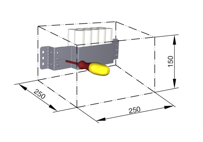
Space required for commissioning and maintenance
Sufficient space must be kept clear near any attachments to allow for commissioning and maintenance. It may be necessary to provide sufficiently sized inspection access openings.
Space requirement, control component on one side
VARYCONTROL | |||
Easy controller | 250 | 200 | 300 |
Compact controller | 250 | 200 | 250 |
Universal controller, dynamic | 520 | 250 | 250 |
LABCONTROL | |||
EASYLAB | 550 | 350 | 400 |
Space requirement, control components on two sides
VARYCONTROL | ||||||
Universal controller, static | 520 | 250 | 250 | 250 | 150 | 250 |
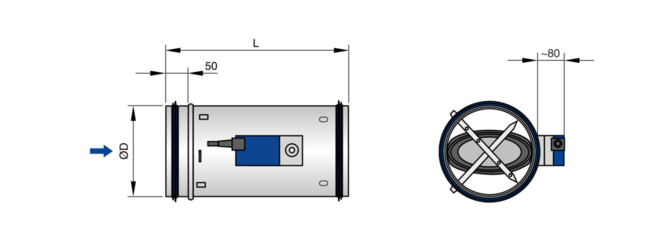
Principal dimensions
ØD [mm]
VAV terminal units made of stainless steel: Outside diameter of the spigot
VAV terminal units made of plastic: Inside diameter of the connecting spigot
ØD₁ [mm]
Pitch circle diameter of flanges
ØD₂ [mm]
Outside diameter of flanges
ØD₄ [mm]
Inside diameter of the screw holes of flanges
L [mm]
Length of unit including connecting spigot
L₁ [mm]
Length of casing or acoustic cladding
B [mm]
Duct width
B₁ [mm]
Screw hole pitch of flange (horizontal)
B₂ [mm]
Outside dimension of flange (width)
B₃ [mm]
Width of device
H [mm]
Duct height
H₁ [mm]
Screw hole pitch of flange (vertical)
H₂ [mm]
Outside dimension of flange (height)
H₃ [mm]
Unit height
n [ ]
Number of flange screw holes
T [mm]
Flange thickness
m [kg]
Unit weight including the minimum required attachments (e.g. Compact controller)
Acoustic data
fm [Hz]
Octave band centre frequency
LPA [dB(A)]
A-weighted sound pressure level of air-regenerated noise of the VAV terminal unit, system attenuation taken into account
LPA1 [dB(A)]
A-weighted sound pressure level of air-regenerated noise of the VAV terminal unit with secondary silencer, system attenuation taken into account
LPA2 [dB(A)]
A-weighted sound pressure level of case-regenerated noise of the VAV terminal unit, system attenuation taken into account
LPA3 [dB(A)]
A-weighted sound pressure level of case-regenerated noise of the VAV terminal unit with acoustic cladding, system attenuation taken into account
All sound pressure levels are based on 20 μPa.
Volume flow rates
Vnom [m³/h] and [l/s]
Nominal volume flow rate (100 %)
Vmin unit [m³/h] and [l/s]
Technically possible minimum volume flow rate
Vmax [m³/h] and [l/s]
Upper limit of the operating range for the VAV terminal unit that can be set by customers
Vmin [m³/h] and [l/s]
Lower limit of the operating range for the VAV terminal unit that can be set by customers
V [m³/h] and [l/s]
Volume flow rate
ΔV [± %]
Volume flow rate tolerance from setpoint value
ΔVwarm [± %]
Volume flow rate tolerance for the warm air flow of dual duct terminal units
Differential pressure
Δpst [Pa]
Static differential pressure
Δpst min [Pa]
Static differential pressure, minimum
Construction
Galvanised sheet steel
Powder-coated surface (P1)
Stainless steel (A2)
Share page
Recommend this page
Recommend this page by sending a link by mail.
Share page
Thank you for your recommendation!
Your recommendation has been sent and should arrive shortly.
Contact
We are here for you

Please specify your message and type of request.
Tel.: +60 6 678 8188 | Fax: +60 6 678 8288 (388)
Contact
Thank you for your message!
Your message is send and will be processed shortly.
Our department for Service-Requests will contact you asap.
For general question regarding products or services you can also call:
Tel.: +60 6 678 8188 | Fax: +60 6 678 8288 (388)
Contact
We are here for you
Please specify your message and type of request.
Tel.: +60 6 678 8188 | Fax: +60 6 678 8288 (388)
Contact
Thank you for your message!
Your message is send and will be processed shortly.
Our department for Service-Requests will contact you asap.
For general question regarding products or services you can also call:
Tel.: +60 6 678 8188 | Fax: +60 6 678 8288 (388)